In India, corrosion causes significant economic losses across oil & gas pipelines, refineries, and infrastructure, making effective corrosion control essential for asset reliability and longevity.
One of the most effective mitigation strategies is cathodic protection, where pipelines are electrically controlled to prevent metal loss. Within this system, the monolithic insulation joint cathodic protection plays a critical engineering role by electrically isolating pipeline sections while maintaining full mechanical strength. These components ensure that cathodic protection current is correctly directed, preventing stray current interference and corrosion hotspots.
For EPC engineers and pipeline designers, understanding the design, installation, and standards governing these joints is essential for long-term pipeline integrity and compliance with global pipeline corrosion prevention practices.
What is a Monolithic Insulation Joint in Cathodic Protection Systems?
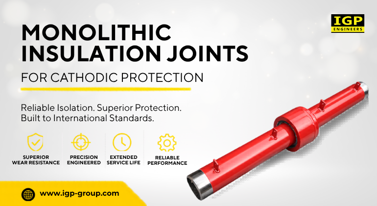
A monolithic insulation joint component is a factory-fabricated, welded pipeline assembly that provides permanent electrical isolation between two pipeline sections while maintaining full pressure containment and structural continuity.
Unlike field-assembled insulating joints, MIJs are constructed as a single integrated unit, eliminating weak points that can lead to leakage or insulation failure. This makes them highly reliable in high-pressure transmission pipelines, subsea systems, and buried cross-country networks.
The Setup:
In this setup, the joint ensures that cathodic protection current is confined to designated pipeline sections, improving system efficiency and reducing interference from external electrical sources. The concept is closely related to the insulating flange joint, but MIJs are preferred in high-integrity systems due to their welded monolithic construction, which reduces maintenance risks and enhances durability.
From a system perspective, the monolithic insulation joint cathodic protection approach ensures electrical segmentation, optimized current distribution, and long-term structural reliability in harsh environments.
Design Parameters of MIJ Systems
The effectiveness of an MIJ depends heavily on its engineering design. The insulating joint design pipeline process involves balancing electrical isolation with mechanical strength and environmental resistance. Key design considerations include:
1. Electrical Design Factors
- High dielectric strength insulation materials
- Stable insulation resistance under pressure and temperature variations
- Controlled leakage current limits for cathodic protection efficiency
2. Mechanical Design Factors
- Axial load resistance under pipeline pressure
- Bending and torsional stress handling
- Weld integrity in high-stress zones
3. Material and Coating Selection
- API-grade carbon steel body construction
- Epoxy or phenolic resin insulation systems
- External anti-corrosion coatings such as FBE or 3LPE
Engineers often evaluate insulating joint design pipeline specifications based on project pressure class, fluid type, and environmental exposure. For oil and gas transmission systems, adherence to MIJ specification oil gas requirements ensures compatibility with global EPC standards.
Proper design is essential because any mismatch in electrical or mechanical parameters can compromise monolithic insulation joint cathodic protection performance and lead to system-wide inefficiencies.
Pressure and Temperature Ratings
MIJs are designed for extreme operational environments found in modern insulating joint design pipeline. Depending on application, they can support:
- Low-pressure distribution networks
- High-pressure crude oil and gas transmission lines
- Subsea offshore pipeline systems
Temperature resistance typically ranges from -20°C to +120°C, with specialized designs capable of exceeding these limits for thermal processing pipelines.
Pressure and thermal stability are critical because fluctuations can affect insulation integrity and mechanical bonding. Proper selection aligned with MIJ pipeline installation standards ensures long-term reliability under dynamic operating conditions.
In offshore and buried applications, environmental stress further increases design complexity, making engineering validation essential for sustained efficiency.
MIJ Pipeline Installation Standards
Correct installation is one of the most critical success factors in MIJ performance. Even a perfectly designed joint can fail if installation procedures are not strictly followed. The MIJ pipeline installation standards typically include the following steps:
1. Pre-Installation Inspection
Check insulation resistance, visually inspect for transport or coating damage before installation to ensure proper condition and readiness.
2. Pipeline Alignment
Ensure correct axial and angular alignment to prevent stress concentration and prepare the joint for accurate, controlled welding operations.
3. Welding Procedure Control
Use low heat input welding methods and strictly follow approved WPS to protect insulation layers from thermal damage.
4. Post-Weld Integrity Check
Inspect insulation after welding to confirm integrity and ensure dielectric materials are not degraded by heat exposure.
5. Coating Restoration
Apply field joint coating systems properly to restore corrosion protection and maintain long-term pipeline durability and performance.
These MIJ pipeline installation standards are essential to avoid insulation breakdown and maintain long-term cathodic protection efficiency.
Incorrect installation is one of the leading causes of failure in monolithic insulation joint cathodic protection systems, especially in field conditions where environmental control is limited.
Testing and Quality Assurance After Installation
Once installed, MIJs undergo rigorous testing to ensure compliance with engineering and safety standards.
Electrical Testing
- Insulation resistance (Megger testing)
- High-voltage dielectric testing
Mechanical Testing
- Hydrostatic pressure testing
- Load and stress verification under simulated conditions
Non-Destructive Testing (NDT)
- Ultrasonic testing of weld joints
- Radiographic inspection for internal defects
These validation steps ensure compliance with cathodic protection pipeline standards and reduce operational risks in long-term service. Proper testing also confirms that the monolithic insulation joint cathodic protection system is functioning as intended without leakage or electrical bridging.
International Standards for Cathodic Protection Systems
MIJs must comply with globally recognized engineering standards to ensure safety, interoperability, and performance reliability.
NACE SP0169
NACE SP0169, currently maintained by AMPP as SP0169-2024, is a globally recognized standard for managing external corrosion in buried and submerged metallic pipeline systems. It outlines best practices for corrosion mitigation through protective coatings, cathodic protection (CP), electrical isolation, inspection, monitoring, and stray current control.
The standard aims to enhance long-term pipeline reliability and integrity by integrating:
- High-performance protective coating systems
- Effective cathodic protection (CP) measures
- Electrical isolation solutions
- Continuous corrosion monitoring and maintenance strategies
ISO 15589
ISO 15589 is a globally recognized standard that outlines the requirements and best practices for the design, installation, operation, testing, inspection, and maintenance of cathodic protection (CP) systems for pipeline networks in the oil, gas, petrochemical, and energy sectors. Its primary objective is to safeguard buried, submerged, and landfall pipelines against external corrosion by ensuring effective cathodic protection throughout their service life.
Key Areas Covered by ISO 15589
- Cathodic protection system design and performance requirements
- Electrical continuity and isolation guidelines
- Compatibility between protective coatings and CP systems
- Electrical isolation of pipeline sections from connected structures, facilities, and grounding systems
EN 12954
EN 12954 is a European standard titled “Cathodic protection of buried or immersed metallic structures, General principles and application for pipelines.” It defines the general principles for designing, implementing, operating, and maintaining cathodic protection (CP) systems for buried and submerged pipelines and related metallic structures.
- Ensures long-term corrosion control of metallic structures
- Maintains a protective electrochemical potential on the metal surface
- Prevents corrosion reactions in soil and water environments
- Supports continuous cathodic protection performance over time
These frameworks define the acceptable performance parameters for pipeline corrosion prevention systems and ensure uniformity across global EPC projects.
Compliance with these standards helps ensure reliable electrical isolation, effective cathodic protection, improved pipeline integrity, and long-term corrosion prevention in critical infrastructure systems.
Brief comparison of Monolithic Insulation Joints vs Insulation Flange Kits
Monolithic Insulation Joints and Insulation Flange Kits both provide pipeline electrical isolation for cathodic protection systems, but differ significantly in design, installation method, pressure capability, and long-term reliability performance.
|
Aspect |
Monolithic Insulation Joint (MIJ) |
Insulation Flange Kit |
|
Structural Design |
Factory-fabricated, welded monolithic pipeline section | Flanged joint assembled using gasket, sleeves, and insulating kits |
|
Electrical Isolation |
Permanent, high-integrity electrical isolation |
Dependent on gasket and assembly quality; can degrade over time |
|
Pressure Handling |
Suitable for high-pressure transmission and subsea pipelines |
Generally used in low to medium pressure applications |
|
Installation Method |
Installed as a welded pipeline segment in field |
Assembled using bolted flange connections on-site |
|
Reliability in Cathodic Protection |
High reliability for long-term cathodic protection performance |
Moderate reliability; requires periodic inspection and maintenance |
Overall, Monolithic Insulation Joints offer superior structural integrity and reliability for high-pressure pipelines, while Insulation Flange Kits suit simpler applications, making selection dependent on design requirements and operating conditions.
Why IGP Engineers is the Preferred Choice for MIJs
At IGP Engineers, we are recognized as a preferred Monolithic Insulation Joints manufacturer by delivering precision engineering, uncompromised quality, and long-term reliability. Our MIJs are engineered for effective electrical isolation and superior structural strength in critical pipeline applications.
As a trusted provider of pipeline insulation solutions, we adhere to strict international standards, advanced manufacturing practices, and rigorous testing procedures to ensure consistent performance. With a strong focus on safety, durability, and client satisfaction, we serve the demanding requirements of the oil, gas, petrochemical, and process industries.
Final Words
Monolithic insulation joints are critical for maintaining pipeline integrity by providing reliable electrical isolation and supporting effective cathodic protection in demanding service conditions. Proper engineering design, correct installation practices, and compliance with standards such as NACE SP0169 significantly reduce corrosion risks and enhance asset life.
We deliver certified MIJs for oil, gas, and infrastructure applications, backed by verified quality systems and project capabilities in the infrastructure sector Infrastructure Solutions and internationally recognized certifications Certifications, ensuring dependable performance across critical pipeline networks.
Partner with IGP Engineers for certified Monolithic Insulation Joints designed to improve pipeline reliability and support long-term cathodic protection.